Blade selection
Circular saw blade diameter and bore: checking compatibility
At a glance
Compatibility depends on three specifications. Diameter must remain within the cutting unit's permitted maximum, the bore must match the spindle exactly, and any additional pin-hole pattern must match the flange. If one of these checks fails, the blade either cannot be fitted or cannot operate correctly and safely.
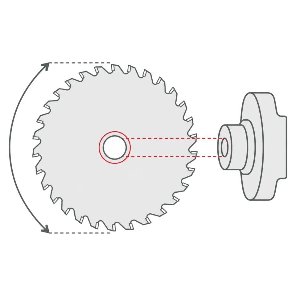
Diameter is not just a matter of available space
The machine's maximum blade diameter is a safety limit, not simply a clearance dimension. At the same rotational speed, a larger blade has a higher peripheral speed, which is why maximum permitted rpm decreases as diameter increases. Exceeding the limit changes the blade's operating conditions, impairs the cut and is dangerous.
The manufacturer's general reference table starts at 23,000 rpm for 100 mm and falls to 2,250 rpm for 800 mm. Intermediate reference values include 8,000 rpm at 250 mm, 6,500 at 300 mm, 5,500 at 350 mm and 3,100 at 600 mm. These are useful initial checks when markings on a fitted blade are unreadable.
A family-specific lower limit always takes precedence. LU6A dry-cut steel blades operate at much lower speeds: 3,200 rpm at 160 mm, 1,900 at 250 mm, 1,800 at 300 mm and 1,600 at 355 mm. At 300 mm that is 1,800 rather than the 6,500 rpm general reference.
A smaller diameter may be possible within the cutting unit's mechanical limits, but reduces cutting depth and peripheral speed. Never exceed the stated diameter, even if the guard appears to provide physical clearance.
The bore is a precision fit, not an approximate dimension
The central bore must match the spindle without appreciable play. Even a small discrepancy creates eccentricity, which becomes visible on the cut edge and often audible in the machine.
The catalogue includes 21 bore sizes: 15.88, 16, 20, 22, 25, 25.4, 30, 32, 35, 40, 45, 50, 50.8, 55, 60, 65, 70, 75, 80, 90 and 100 mm. They correspond to real machine spindles rather than a range of tolerances. Decimal sizes often reveal an imperial origin: 15.88 mm is 5/8 inch, 25.4 mm is one inch and 50.8 mm is two inches. LSBX for horizontal panel sizing saws reaches a 100 mm bore, while LU2A spans 20 to 80 mm across its 150 to 760 mm range.
LU6A, for example, includes product codes with 15.88 or 25.4 mm bores for machines built to imperial standards. A 16 mm bore is not an equivalent substitute for 15.88 mm.
Drive features at a glance
Many industrial machines do not transmit torque through friction at the central bore alone. Pins or keys on the flange require matching features on the blade. Tables identify them as NL or KN, sometimes grouped in an FT pattern.
| Code | Meaning | How to read it |
|---|---|---|
| NL | Drive-pin holes | Quantity / hole diameter / pitch-circle diameter. 2/9/46.4 means two 9 mm holes on a 46.4 mm pitch circle |
| KN | Drive keyway | Width × depth in millimetres. 10 × 4 is 10 mm wide and 4 mm deep |
| FT01 | Combined pattern | 2/7/42 + 2/9/46.4 + 2/10/60: three different patterns on one blade |
| FT02 | Combined pattern | 2/9/46.4 + 2/10/60: FT01 without the 42 mm pitch circle |
| FT03 | Combined pattern | 2/7/42 + 2/10/60, found on construction blades |
| 4CH 21×5 | Four drive keyways | Four 21 × 5 mm keyways, typical of multiripping machines |
FT patterns combine several hole layouts on one blade to suit different flanges. FT01 includes the patterns contained in FT02, but FT02 does not include the additional 2/7/42 pattern.
The blade mounting matters as much as the blade
Clamping flanges must have the same diameter, be as large as practical and never be smaller than one third of blade diameter. A 300 mm blade therefore requires flanges of at least 100 mm. Undersized flanges are a common cause of unstable or wavy cuts.
The flange faces must also be parallel. Diameter, faces and concentricity are checked with a dial indicator, not by eye. If the blade runs eccentrically despite the correct bore, inspect the mounting system.
The spindle must be straight and within h7 tolerance. A correct bore cannot compensate for a spindle that is out of tolerance.
Spacer rings follow the same rule: they must be parallel and clean. Even a thin resin deposit between spacer and flange introduces run-out that becomes significant at operating speed.
Compatibility checks in the correct order
-
Read the blade already fitted
Diameter, bore, kerf and maximum rpm are marked on the plate. This is the fastest reference if the fitted blade is known to be correct.
-
Check maximum diameter on the cutting unit
Compare it with the guard and the full lifting travel, not merely the visible clearance. A blade that touches the riving knife or scoring unit cannot be used.
-
Measure the spindle, not the old blade
An old blade may already contain an unsuitable adapter. A calliper measurement on the clean spindle is the reliable reference.
-
Photograph and measure the flange
Count the pins, measure their diameter and pitch circle: this is NL notation. For a key, measure keyway width and depth: this is KN. Those values identify FT01, FT02, FT03 or a machine-specific pattern.
-
Inspect the flanges
They must have equal diameters, be at least one third of blade diameter, and have clean, parallel faces. This frequently explains a wavy cut with a new blade.
-
Compare operating speed
Machine rpm must remain below the limit for that diameter. Use a family-specific table where present, particularly for dry-cut steel blades, whose limits are much lower.
-
Check kerf compatibility
On a squaring saw with a scoring blade, the main blade and scoring width must match. A conical scoring blade is adjusted by height; approximately every millimetre of vertical movement changes scoring width by 0.25 mm.
Dimensional ranges of selected families
These ranges help identify where to search for a combination. They describe a whole family, not an individual product code.
| Family | Diameter (mm) | Bore (mm) | Application |
|---|---|---|---|
| LI25M | 80–340 | 16–80 | Conical scoring blades for horizontal panel sizing and squaring saws |
| LU1D | 250–350 | 30–70 | Ripping and gang cutting solid wood, including 4CH 21×5 keyways |
| LU2A | 150–760 | 20–80 | Ripping and crosscutting panels |
| LSBX | 250–720 | 30–100 | Industrial panel sizing on horizontal machines |
| LU6A | 160–355 | 15.88–30 | Dry cutting steel tubes and profiles |
A family range tells you where to search. The exact diameter-and-bore combination exists only at product-code level.
Common mistakes
-
Stopping at diameter and bore
On industrial panel sizing blades, also check angles and mounting holes specified for the machine. An LSBX with the correct diameter and bore may still not be the configuration approved by the machine manufacturer.
-
Improvising a bore adapter
Precision reduction bushes exist for specified combinations. Improvised solutions introduce eccentricity, widen the cut and load the machine bearings.
-
Confusing NL and KN
NL denotes round pin holes; KN denotes a keyway measured width by depth. The 4CH 21×5 keyways used on multiripping machines cannot be replaced by an FT01 or FT02 round-hole pattern.
-
Fitting a scoring blade without checking width
If the score is narrower than the main kerf, the coating still chips; if too wide, it leaves a visible step. Adjust in small increments and test on scrap material.
Frequently asked questions
01 Can I fit a blade smaller than the machine's maximum diameter?
Yes, if the cutting unit allows it mechanically, but usable cutting depth and peripheral speed decrease. On a squaring saw this may prevent cutting the same stack thickness as before.
02 What exactly does 2/9/46.4 mean?
It is an NL drive-hole specification: two holes, each 9 mm in diameter, arranged on a 46.4 mm pitch circle around the central bore.
03 What is the difference between FT01 and FT02?
FT02 contains 2/9/46.4 and 2/10/60. FT01 adds 2/7/42. FT01 therefore covers every flange pattern included in FT02 plus the 42 mm pattern.
04 Can a 15.88 mm bore be enlarged to 16 mm?
Not as an improvised modification. 15.88 mm is 5/8 inch and is a design dimension used on some LU6A codes for imperial machines, not a tolerance of a 16 mm bore.
05 How do I know whether drive-pin holes are required?
Inspect the flange with the blade removed. Any pins beyond the central spindle require matching holes. A smooth flange transmits torque by friction and normally requires only the correct bore and clamping.
06 Why does the same family contain different bores?
Because it covers different machines. LU2A spans applications from portable saws to horizontal panel sizing machines and therefore uses distinct product codes with bores from 20 to 80 mm.
07 Does maximum rpm change with diameter?
Yes, it decreases as diameter increases. The general reference runs from 23,000 rpm at 100 mm to 2,250 rpm at 800 mm. Some families have lower specific limits, such as dry-cut steel blades.
08 The blade runs eccentrically: is the bore at fault?
Possibly, but also inspect the spindle and flanges. Flanges must be equal, parallel, clean and at least one third of blade diameter; the spindle must be straight and within h7 tolerance. Resin on a flange can mimic an incorrect bore.
Technical review
Filippo Perissinotto
Technical reviewer for wood and wood-based materials
Graduate in Wood Technology and Industries, technical consultant and wood-sector specialist.
The review covers the accuracy, clarity and consistency of information relating to wood and wood-based materials. Tool setup, machine operation and safety must always be checked against the manufacturer’s documentation and instructions.
Profile, qualifications and review methodRelated guides