Blade selection
Circular saw blade technical glossary
At a glance
Circular saw blade tables use a recurring set of symbols: D for diameter, B for kerf, b for plate thickness, d for bore and Z for tooth count. These are accompanied by tooth-geometry abbreviations and mounting-hole patterns.
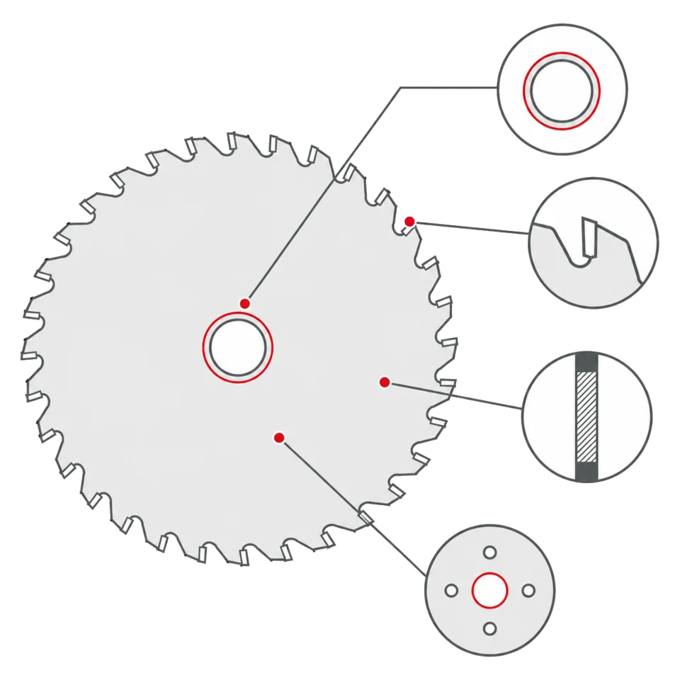
Dimensions and table symbols
- DiameterD
- Outside blade diameter measured at the tooth tips, in millimetres. It is determined by the machine cutting unit and must never exceed the stated maximum because it affects peripheral speed and permitted rpm. Catalogue sizes run from 80 mm scoring blades to 760 mm panel sizing blades.
- KerfB
- Width of the slot left in the material, measured across the teeth. It determines waste and power demand: thin-kerf blades can be 2.2 mm, while industrial panel sizing blades reach 6.4 mm. On scoring blades it may be an adjustable range rather than one value.
- Plate thicknessb
- Thickness of the steel plate without the teeth. It is always less than B; the difference provides side clearance so the plate does not rub against the cut walls. A plate that is too thin for its diameter can deflect under load.
- Bored
- Diameter of the central hole fitting the blade to the machine spindle, in millimetres. It must match exactly. Imperial-derived sizes such as 15.88 and 25.4 mm are common on some machines.
- Tooth countZ
- Number of teeth on the blade. Catalogue families range from 16 teeth on gang-cutting blades to 168 on crosscut blades. Some notations also include non-cutting stabilising teeth or the combined teeth of a two-part scoring set.
- PitchP
- Distance between adjacent teeth along the circumference. It connects material thickness and tooth count. One manufacturer formula estimates P = S × 1.4142 / 3 for roughly three engaged teeth, then Z = D × 3.14 / P.
- Engaged teeth
- Teeth simultaneously inside the material. About three or four is a common starting guideline: fewer can make engagement aggressive, while too many restrict chip evacuation. Use it as an indicative selection aid rather than a universal prescription.
- Maximum rotational speed
- The speed above which the blade must not operate. It decreases as diameter increases: the general reference ranges from 23,000 rpm at 100 mm to 2,250 at 800 mm, including 8,000 at 250 mm and 5,500 at 350 mm. A more restrictive family-specific value always takes precedence.
Tooth geometries
- ATB
- Alternate Top Bevel: successive teeth incline right and left. The leading corner severs surface fibres before they lift, making ATB a reference geometry for solid wood and panels. Bevel angles vary by family.
- TCG
- Triple Chip Grind: a trapezoidal roughing tooth alternates with a flat clearing tooth. Sharing the load protects cutting corners and suits laminates, plastics and non-ferrous metals.
- Triple-chip grind tooth
- The TCG geometry. Hook angle varies by application: positive 5° or 10° on some laminated-panel blades and negative 6° on blades for aluminium, copper and brass extrusions over 3 mm.
- DTCG
- Double Trapezoidal Chip Grind, with trapezoidal form on both faces. It distributes impact across several edges and is used for demanding tasks such as dry cutting steel tubes and profiles and abrasive polymers.
- Flat-top tooth
- A straight cutting edge without bevel. It removes material frontally and leaves a square-bottomed cut. It is used for thin-kerf ripping and, with stabilising teeth, for gang cutting on multiripping machines.
- Bevelled tooth
- A strongly bevelled profile, reaching 45° on some construction blades. It is designed to tolerate occasional contact with nails or staples in structural timber, although repeated metal contact remains abrasive.
- Hook angle
- Inclination of the tooth face relative to the blade radius, often marked α. A positive angle pulls into the cut; a negative angle directs more pressure towards the table. Catalogue values range approximately from +15° to −6°.
- Chip limiter
- A shoulder ahead of the cutting edge that prevents an excessive bite. It limits chip thickness per pass and helps reduce kickback, especially in machine-fed applications.
- Stabilising teeth
- Teeth that do not perform the main cut but help keep a multiripping blade aligned within a stack of material. Z notation may distinguish cutting and stabilising teeth, so they should not all be counted as cutting edges.
Mounting and drive features
- Drive-pin hole
- An additional hole engaged by a flange pin to transmit torque where clamping friction alone is insufficient. A machine designed for drive pins requires a blade with the corresponding holes.
- NL
- Drive-pin-hole notation: quantity / hole diameter / pitch-circle diameter. 2/9/46.4 means two 9 mm holes on a 46.4 mm pitch circle.
- KN
- Drive keyway stated as width × depth in millimetres. 10 × 4 means 10 mm wide and 4 mm deep. A keyway and round drive holes are different systems.
- FT01, FT02 and FT03
- Combined hole layouts. FT01 includes 2/7/42, 2/9/46.4 and 2/10/60; FT02 includes the latter two; FT03 includes 2/7/42 and 2/10/60. FT01 therefore includes the flange patterns covered by FT02, but not vice versa.
- Spindle
- The rotating shaft on which the blade is mounted. It must be straight and within h7 tolerance. An out-of-tolerance spindle prevents concentric mounting even with the correct bore.
- Flange
- The pair of discs clamping the blade to the spindle. They should have equal diameters, be as large as practical and never less than one third of blade diameter, with clean and parallel faces. Check concentricity with a dial indicator.
- Spacer rings
- Rings placed between blade and flange to position the blade on the spindle. They must be parallel and clean; resin between supporting faces creates run-out and a wavy cut.
- Blade projection
- The amount of blade emerging above the workpiece. It must at least accommodate tooth height; changing projection within the machine manufacturer's limits changes the angle at which the tooth enters the material.
- Drive keyways
- Rectangular slots around the central bore. 4CH 21×5 means four 21 × 5 mm keyways, common on multiripping blades. It is not interchangeable with a round-hole pattern.
- Reduction bush
- A precision ring adapting a larger bore to a smaller spindle for an expressly permitted combination. An improvised adapter creates eccentricity, widens the cut and loads machine bearings incorrectly.
Materials, technologies and accessories
- Carbide
- A sintered carbide-based material used for brazed tooth tips. There is no universal grade: catalogue families use different grades for wood, panels, coated materials, plastics, construction timber and steel.
- Carbide grade
- A code identifying tip composition and its balance of hardness and toughness. A harder grade resists abrasion but can be more vulnerable to impact, which is why construction and laminate blades use different grades.
- Anti-vibration slots
- Slots cut into the blade plate, often filled with damping material, to reduce vibration, noise and cut waviness. They are not fitted to every family or every diameter.
- Anti-kickback design
- Blade and tooth design intended to reduce workpiece kickback, found on some ripping families where timber can close on the blade as internal stress is released. It does not replace the riving knife or machine guards.
- Scoring blade
- A small-diameter blade mounted ahead of the main blade. It rotates in the opposite direction and scores the underside coating before the main blade passes, preventing lower-edge chipping on melamine-faced panels.
- Adjustable scoring blade
- A two-part scoring set whose kerf is adjusted with spacer rings between the elements; some designs adjust on the machine without loose spacers. Stated Z is the sum of both discs.
- Conical scoring blade
- A one-piece conical scorer whose cutting width is adjusted by changing height relative to the table. Approximately every millimetre of vertical movement changes score width by 0.25 mm, so adjustment should be gradual.
- Negative hook
- A negative hook angle directs cutting pressure towards the table rather than lifting the workpiece. This allows suitable blades to operate above the material while keeping panels against their support.
- Resharpening
- Restoring the cutting edge as soon as it becomes dull, while preserving original tooth angles with suitable grinding wheels and coolant. Excessive or hand grinding behind the tooth risks tip failure and loss of balance.
- Family and product code
- A family defines carbide grade, tooth geometry, hook angle and application. A product code is one dimensional configuration within that design. One family can contain from a few to more than a hundred product codes sharing the same cutting principle.
Frequently asked questions
01 What is the difference between B and b?
B is kerf, the slot width measured across the teeth; b is steel plate thickness. B is always greater than b, providing the clearance that keeps the plate from rubbing against the cut walls.
02 What exactly does Z indicate?
Blade tooth count. On multiripping blades notation may separate cutting and stabilising teeth; on two-part scoring sets the stated value can be the sum of both discs.
03 Are ATB and TCG interchangeable?
No. ATB severs wood fibres with an inclined edge. TCG distributes load between trapezoidal and flat teeth and suits hard, abrasive or coated materials. TCG offers no automatic advantage when ripping solid wood.
04 What does 2/10/60 mean?
An NL drive-hole pattern: two 10 mm holes on a 60 mm pitch circle. A value such as 10 × 4 is instead a KN keyway 10 mm wide and 4 mm deep.
05 Do all blades have anti-vibration technology?
No. It is used on many families but not all, and on some ranges only above a certain diameter, often 230 or 250 mm.
06 Is carbide grade more important than tooth geometry?
They work together. Geometry determines how the tooth enters the material; grade affects how long the edge maintains that action. Abrasive materials make grade particularly important for service life.
07 Is a chip limiter useful only on automatic machines?
Its benefit is greatest where feed is machine-controlled, but in manual work it can also limit how aggressively the tooth bites if the workpiece closes on the cut.
08 Is a scoring blade always required on coated panels?
Not always. Some negative-hook families are designed to work without one within specified thickness limits. Outside those applications, a scoring blade remains the most reliable solution for melamine-faced panels.
Technical review
Filippo Perissinotto
Technical reviewer for wood and wood-based materials
Graduate in Wood Technology and Industries, technical consultant and wood-sector specialist.
The review covers the accuracy, clarity and consistency of information relating to wood and wood-based materials. Tool setup, machine operation and safety must always be checked against the manufacturer’s documentation and instructions.
Profile, qualifications and review methodRelated guides