Materials
Plexiglas and plastic materials: how to cut them
At a glance
Engineering plastics fall into two groups with different behaviour: rigid, brittle materials such as Plexiglas can chip, while tough polymers can deform and re-fuse. In both cases frictional heat is the central problem. The appropriate blade generally uses triple-chip geometry, a negative or modest hook angle, a high tooth count and a steady feed that must not be allowed to stall.
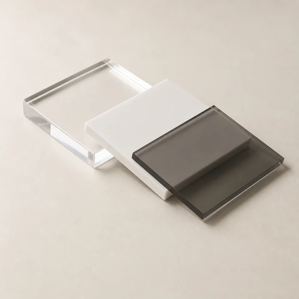
Two groups with different cutting requirements
The word plastic covers materials that behave very differently under a saw tooth, so the first step is to identify the group.
The first group is rigid and brittle: Plexiglas (PMMA), solid polycarbonate, polystyrene and rigid PVC. They are hard at the surface and do not deform much under stress; they fracture. Typical defects are edge chipping and, in severe cases, cracks propagating from the cut.
The second group is tough and deformable: polyethylene, polypropylene, polyamide, solid-surface products and other engineering polymers. They tend not to chip, but can stretch beneath the tooth, produce stringy chips and leave a burr.
Both groups are sensitive to heat. Plastics soften at far lower temperatures than the other catalogue materials. Heat can create internal stress and microcracks in brittle plastics, while tough polymers can re-fuse behind the blade and close onto the plate. Preventing friction is therefore fundamental.
How common plastic materials behave
Behaviour under the tooth matters more than the trade name.
| Material | Behaviour | Typical defect | What is required |
|---|---|---|---|
| Plexiglas (PMMA) | Rigid, brittle and sensitive to internal stress | Edge chipping and microcracks | Fine tooth pitch, negative hook and steady feed |
| Solid polycarbonate | Rigid but tougher than PMMA | Cloudy edge from overheating | Fine tooth pitch and a cool cut |
| Rigid PVC | Rigid and often mineral-filled | Chipped edge and cutting-edge wear | TCG geometry and wear-resistant carbide |
| Polyethylene and polypropylene | Tough and deformable | Stringy chips and edge burr | Large enough gullets and sustained feed |
| Solid surface and engineering polymers | Dense, homogeneous and sometimes mineral-filled | Cut re-fusing when heat builds | Moderate positive hook and constant speed |
| Thermoplastic panel composites | Behaviour varies with formulation | Irregular edge between different layers | Neutral geometries intended for laminates and plastics |
Many engineering plastics contain mineral fillers that make them abrasive. Their effect on carbide life can resemble that of a coated panel.
Slowing the feed is often the wrong remedy
When an edge deteriorates, the instinctive reaction is to reduce feed. On plastics this is often counterproductive: a slow feed makes the tooth rub instead of cut, creating the very heat that must be avoided.
In a brittle material that heat can release internal stresses and form microcracks; in a tough polymer it melts the edge and closes the slot behind the blade. If quality deteriorates, first check edge sharpness and rotational speed, then maintain—or where appropriate increase—a steady feed rather than pausing in the cut.
The ideal cutting setup for plastics
Six checks that apply to both groups unless stated otherwise.
-
Triple-chip grind geometry
This is the reference geometry across the catalogue families intended for plastics. The trapezoidal tooth opens the cut and protects its corners; the flat tooth clears the bottom in the opened slot. It limits chipping in brittle material and reduces tearing in tougher polymers.
-
Negative hook for brittle plastics, modest positive hook for tough polymers
Dedicated families for brittle Plexiglas work around −3°, helping restrain the workpiece rather than lifting it. Engineering polymers and solid-surface materials can use about +5° to assist entry without excessive rubbing.
-
A high tooth count
Dedicated plastic blades are commonly around Z96 at 300 mm. Each tooth removes little material, reducing local load and helping maintain continuous engagement in thin sheet.
-
A moderate kerf
Removing less material reduces friction and heat, and also limits vibration in thin sheet. The same principle applies to non-ferrous metals, which share much of the same geometric approach.
-
Steady, sustained feed
Feed is one of the strongest determinants of the result. It must remain uniform throughout the cut: hesitation leaves visible marks and a pause can overheat or melt the edge.
-
Rigid sheet support
Plastic sheet, particularly below 5 mm, vibrates easily. Continuous support close to the cutting line prevents edge scoring and reduces crack propagation in brittle materials.
Where these features appear in the catalogue
The following families list plastic or polymer materials among their declared applications.
| Family | Geometry and hook angle | Teeth at 300 mm | Appropriate use |
|---|---|---|---|
| LU4A | TCG, −3° | 96 | Dedicated family for Plexiglas and rigid plastics |
| LU4D | TCG, +5° | Not available | Engineering polymers and solid-surface materials |
| LU3F | TCG, −3° | 96 | Two-sided laminates and plastics |
| LU5B | TCG, +5° | 88 and 96 | Non-ferrous metals and plastics with one blade |
| LU5D | TCG, −6° | 96 | Tubes and profiles, including rigid PVC |
| LU2C | ATB, H00K carbide | 96 and 120 | Crosscutting thermoplastic panel composites |
| LSBX | Flat/trapezoidal sequence, variable angles | 60 to 96 | Industrial panel sizing, including Plexiglas sheet |
| FRMPI | HLTCG with a bevel on the second tooth, 0° | Not available | Mixed construction applications including plastics |
Common mistakes
-
Slowing down when the edge deteriorates
A slow feed causes rubbing, rubbing creates heat, and heat causes both microcracking in brittle plastics and re-fusing in tough ones.
-
Increasing rpm to improve the finish
More peripheral speed means more frictional heat. Use a suitable operating range for the material while always remaining within blade and machine limits.
-
Using a wood blade on Plexiglas
A low tooth count and strongly positive hook can grab and chip brittle sheet. If thin sheet is not correctly supported it may fracture during cutting.
-
Removing the protective film before cutting
Leave the film on transparent sheets until machining is complete. It protects against support and sliding marks that would remain permanently visible.
-
Treating every plastic in the same way
Plexiglas and polyethylene require different hook-angle choices. First decide whether the material is rigid and brittle or tough and deformable.
Frequently asked questions
01 Why does Plexiglas chip at the edge?
It is rigid and brittle: under stress it fractures rather than deforming. TCG geometry, a negative hook angle, fine tooth pitch and firm support reduce the tendency for cracks to start and propagate.
02 What does it mean when plastic re-fuses in the cut?
Frictional heat exceeds the polymer's softening temperature. The material becomes plastic again and closes behind the blade, increasing friction further. A sharp blade, suitable speed and steady feed keep the cut cooler.
03 Should I slow the feed when cutting plastics?
Usually no. Excessively slow feed makes teeth rub and generate heat. Maintain a steady, sufficiently positive feed and adapt rpm, tooth count and support to the material and machine.
04 Do Plexiglas and engineering polymers need different blades?
The main distinction is hook angle. Rigid brittle plastics often use about −3° to restrain the sheet, while tough polymers and solid-surface materials may use a modest positive angle around +5°.
05 Why do plastic blades resemble aluminium blades?
Both applications are sensitive to heat and adhesion. TCG geometry breaks chips and protects cutting corners, so some families are declared for both non-ferrous metals and plastics.
06 Do plastics wear the cutting edge?
Pure polymers are not highly abrasive, but many engineering plastics contain mineral fillers. These can wear carbide at a rate comparable with coated panels, making carbide grade important.
07 How many teeth are suitable for 10 mm Plexiglas sheet?
A high count is appropriate: dedicated families reach Z96 at 300 mm. The aim is small material removal per tooth and low local load, combined with a sharp edge and steady feed.
08 Should protective film be removed before cutting?
No. Leave it in place until machining is complete so it protects the transparent surface from support and sliding marks.
Technical review
Filippo Perissinotto
Technical reviewer for wood and wood-based materials
Graduate in Wood Technology and Industries, technical consultant and wood-sector specialist.
The review covers the accuracy, clarity and consistency of information relating to wood and wood-based materials. Tool setup, machine operation and safety must always be checked against the manufacturer’s documentation and instructions.
Profile, qualifications and review methodRelated guides