Materials
HPL high-pressure laminate: how to choose a blade
At a glance
HPL consists of resin-impregnated paper layers consolidated under high pressure and temperature into a dense, hard and abrasive material. Compact HPL is the panel itself rather than a thin coating on a wood core. A suitable blade uses TCG geometry to protect tooth corners, a zero or negative hook angle where required by the machine, and an abrasion-resistant carbide grade.
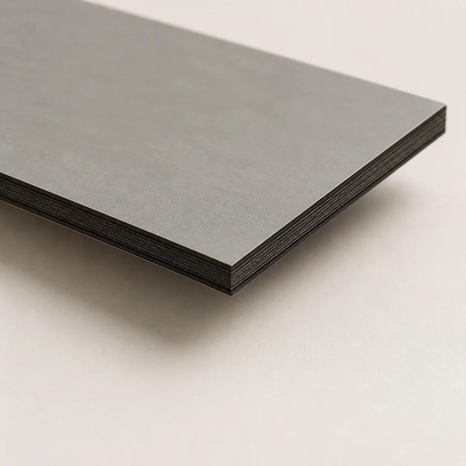
A material made entirely of laminate
HPL means High Pressure Laminate. Layers of kraft paper impregnated with phenolic resin are topped with decorative paper and a protective overlay, then consolidated under high temperature and pressure. The cured result is a rigid, dense and chemically stable composite rather than paper.
This differs fundamentally from a melamine-faced board. On a faced board the decorative layer is only a fraction of a millimetre thick over chipboard or MDF, so most of the cut passes through the substrate. In compact HPL, the same paper-and-resin structure extends through the full thickness.
Compact HPL therefore behaves similarly on entry and exit. Its typical defect is fine corner chipping rather than a large tear in a separate surface layer. Cutting-edge wear is also severe and continuous because cured phenolic resin is highly abrasive.
HPL appears both as self-supporting compact panel for worktops, cladding and technical furniture, and as thin laminate bonded to a substrate. The latter behaves as a coated panel; the former is a material in its own right.
Compact HPL and melamine-faced board
Compact HPL
Laminate throughout its thickness
- The tooth cuts the same material from entry to exit
- Fine corner chipping is more typical than surface tearing
- A scoring blade has little role because there is no separate coating
- Cutting-edge wear is high and continuous
- TCG geometry with zero or negative hook where appropriate
Melamine-faced board
Thin decorative surface over a wood-based substrate
- The tooth crosses two materials with different behaviour
- Exit-side coating tear-out is the typical defect
- A scoring blade addresses the lower-edge problem directly
- Wear depends heavily on the substrate and adhesive
- TCG geometry with a controlled hook angle
Why triple-chip geometry is appropriate
On a hard brittle material, the tooth corners are the most exposed points and the first to lose sharpness. Once rounded, they no longer form a clean edge.
TCG—also marked HLTCG in some technical pages—places a taller bevelled trapezoidal tooth ahead of a slightly lower flat tooth. The trapezoidal tooth opens the slot while protecting its corners; the flat tooth then clears the bottom within the existing slot. Neither carries the full impact on an exposed sharp corner.
The same principle is used for non-ferrous metals because, from the cutting edge's perspective, compact HPL resembles a hard engineering plastic more than a wood panel.
Hook angle depends on the machine: around zero on hand-held and plunge saws, negative on mitre saws cutting from above, and modestly positive on table saws where the workpiece is supported and guided. Strongly positive wood-ripping angles are not appropriate.
Tooth counts used by HPL families
HPL wears the blade even while it appears to cut well
Cured phenolic resin is among the most abrasive materials routinely cut outside metalworking. Wear is continuous and may show little warning until tooth corners are already rounded.
If HPL is processed regularly, set resharpening intervals around that material rather than an average of all panels. A dedicated blade prevents a tool already dulled by HPL from being carried over to less abrasive panels.
The ideal blade and setup for HPL
Five checks. Geometry and carbide grade largely determine cost per metre.
-
Triple-chip grind geometry
The bevelled trapezoidal tooth enters first and protects its corners; the following flat tooth clears the bottom. A fine ATB geometry still exposes sharp corners directly to this abrasive material.
-
Hook angle selected for the machine
Use approximately zero on hand-held and plunge saws, negative on mitre saws cutting downwards, and a modest positive angle on supported table-saw work. The machine determines the direction of cutting force.
-
High but not maximised tooth count
Dedicated families use about Z80 at 250 mm and up to Z96 at 300 mm. Increasing beyond this does not compensate for unsuitable geometry and reduces gullet volume for hot fine dust.
-
Carbide selected for abrasion
HPL families use grades such as H00K, H00XA and H00XF, prioritising wear resistance because the challenge is continuous abrasion rather than impact.
-
Steady feed and a securely supported workpiece
Compact HPL is rigid and records hesitation as aligned microchips. Keep the panel stable and feed continuously through the full cut.
Where these characteristics appear in the catalogue
The following families declare HPL or high-pressure laminate among their applications.
| Family | Geometry and hook | Teeth at 250 mm | Appropriate use |
|---|---|---|---|
| FRHPI | HLTCG, 0° | Not available | HPL with a hand-held or plunge saw |
| FRHT | HLTCG, −3° | 80 | HPL on a mitre saw cutting from above |
| FRHBC | HLTCG, +10° | 80 | HPL on a compact table saw with supported feed |
| LU3F | TCG, −3° | 80 | Two-sided laminates and plastics on industrial machines |
| LSBX | Flat/trapezoidal sequence, variable angles | 60 and 80 | Industrial sizing of HPL and Plexiglas |
Portable HPL families all use HW H00K carbide; their principal difference is hook angle for the machine configuration.
Common mistakes
-
Treating compact HPL as a thick faced panel
A scoring system intended to open a thin coating does not address a material that is laminate throughout. Compact HPL requires geometry and carbide selected for continuous abrasive cutting.
-
Choosing ATB merely because it has many teeth
Tooth count cannot compensate for geometry. Exposed ATB corners wear rapidly and leave a progressively microchipped edge.
-
Using the same blade for HPL and raw panels
HPL dulls the edge much faster. A blade carried straight from HPL to raw board can already be compromised before the new job starts.
-
Slowing feed when chipping appears
Excessively slow feed increases rubbing and heat. Aligned microchips more often indicate irregular feed, workpiece movement or a worn edge.
-
Waiting for wood-like wear symptoms
HPL wear can be quiet: the corner rounds and the edge gradually deteriorates without a large rise in motor load. Planned inspection and resharpening are preferable to waiting for severe symptoms.
Frequently asked questions
01 What is the difference between HPL and melamine-faced board?
A faced board has a thin decorative layer over chipboard or MDF. Compact HPL consists of paper and phenolic resin throughout. The first presents a coating to score; the second presents continuous abrasion and a tooth-corner protection problem.
02 Is a scoring blade required for HPL?
It has little role on compact HPL because there is no separate thin coating. It becomes useful when thin HPL laminate is bonded to a substrate, where the workpiece behaves as a coated panel.
03 Why does HPL wear the cutting edge so quickly?
Cured phenolic resin is highly abrasive. It continuously rounds tooth corners, which is why dedicated families use wear-resistant carbide grades.
04 Which hook angle is suitable for HPL?
It depends on the machine: approximately zero on hand-held and plunge saws, negative on mitre saws, and modestly positive on table saws. Strong positive wood angles are unsuitable.
05 How many teeth are required for HPL?
Dedicated families use around Z80 at 250 mm and up to Z96 at 300 mm. Geometry matters more than maximising tooth count, and excessive Z reduces chip space.
06 Can an aluminium blade cut HPL?
The geometries are related and may produce an acceptable result, but carbide grade and hook angle are optimised for different behaviour. For recurring work, use the dedicated family.
07 How can corner chipping be reduced?
Use TCG geometry, maintain a steady feed and support and clamp the workpiece. Aligned microchips often indicate movement, irregular feed or a worn cutting edge.
08 Can HPL be cut on a mitre saw?
Yes, with a family designed for it. The negative hook angle helps direct cutting pressure towards the fence and table as the blade enters from above.
Technical review
Filippo Perissinotto
Technical reviewer for wood and wood-based materials
Graduate in Wood Technology and Industries, technical consultant and wood-sector specialist.
The review covers the accuracy, clarity and consistency of information relating to wood and wood-based materials. Tool setup, machine operation and safety must always be checked against the manufacturer’s documentation and instructions.
Profile, qualifications and review methodRelated guides