Materials
Chipboard: structure, cutting behaviour and blade selection
At a glance
Chipboard consists of differently sized wood particles bonded with resin and pressed into layers: coarse in the core and fine at the surfaces. This variation makes the exit edge prone to breaking. A suitable blade uses a medium tooth count, ATB geometry on raw board and abrasion-resistant carbide because the binder contributes heavily to cutting-edge wear.
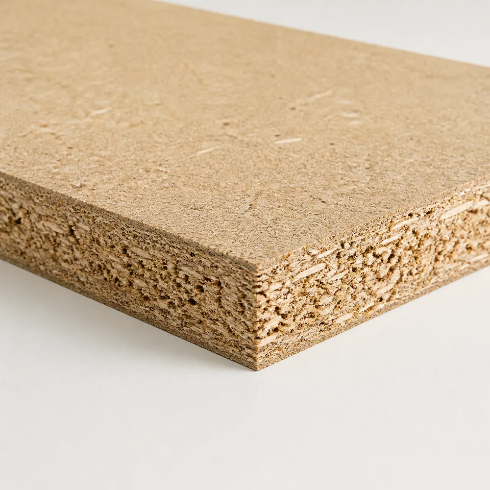
Its heterogeneous structure explains the cutting behaviour
Chipboard turns sawmill and manufacturing residues, small wood and increasingly recovered wood into controlled particles, combines them with resin and hot-presses the mat. This efficient use of raw material helped make industrial furniture affordable.
The structure is not uniform. During forming, fine particles create the surfaces while coarser particles remain in the core. The result has closed, finishable faces but three density zones for the tooth to cross: dense at the top, open in the centre and dense again at the bottom.
The typical defect follows from that structure. Coarse core particles leave microscopic voids; at the exit edge, a surface particle positioned over a void lacks support and is torn out rather than cleanly severed.
Binder also affects tool life. Its high proportion makes the board abrasive, and the tooth alternates between wood and resin-rich zones, creating less uniform wear than in a homogeneous panel.
How chipboard is manufactured
-
Particle preparation
Wood is reduced to controlled particle sizes and classified into fine material for the faces and coarse material for the core.
-
Blending with binder
Particles are sprayed with resin, commonly urea-based for interior use and modified systems for moisture-resistant applications. Binder type and proportion affect abrasiveness.
-
Layered mat forming
Fine particles form the lower face, coarse particles the centre and fine particles the upper face. This creates the different densities crossed by the blade.
-
Hot pressing and calibration
Pressing consolidates the mat and cures the resin. Final calibration brings the panel to thickness and produces flat faces ready for surfacing.
Variants that change cutting behaviour
Chipboard is not one material. Variants affect both edge quality and blade life.
| Variant | What changes | Effect on the edge | Effect on the cutting edge |
|---|---|---|---|
| Standard raw chipboard | Three-layer structure with conventional interior binder | Exit-edge break-out | Progressive but irregular wear between wood and binder |
| Moisture-resistant chipboard | More moisture-resistant binder system | Slightly more cohesive edge | More severe wear from the binder |
| High-density chipboard | Finer particles and greater compaction | A cleaner edge closer to MDF | More abrasive per unit of cut |
| Melamine-faced board | Resin-impregnated decorative surface | The coating chips before the substrate | Surface abrasion adds to binder wear |
| Formwork panel | Film-faced board, often phenolic | Film can lift at the exit edge | Very severe when returned from site with cement residues |
When the panel is coated, the coating determines blade selection and the chipboard substrate becomes secondary.
Why maximising tooth count is not helpful
It is tempting to raise tooth count to close the raw-chipboard edge, copying the approach used for faced panels. The mechanism is different.
Raw chipboard breaks because surface particles lack support over core voids. More teeth do not add support; they reduce gullet volume and retain dust in the cut. This increases heat and can darken the edge.
A medium tooth count corresponding to an appropriate number of engaged teeth is usually more effective. At 300 mm, Z36 to Z72 covers much raw-panel work: remain lower when the edge will be covered and move higher when it remains visible.
A coated panel changes the problem. Geometry must score the surface before removing the substrate; high tooth count then follows from that dedicated cutting system rather than being the solution by itself.
The ideal blade and setup for chipboard
Five checks based on the panel's heterogeneous structure rather than apparent hardness.
-
A calculated medium tooth count
For raw board, Z36 or Z48 at 300 mm suits edges that will be covered; Z60 or Z72 can close a visible edge. Unnecessary additional teeth reduce chip space.
-
Large enough gullets for dust and particles
Chipboard produces fine dust and coarse fragments together. Gullet volume is what carries this mixture out and explains why a coarser pitch can cut cooler.
-
ATB on raw board, TCG on faced board
On an uncoated panel, an inclined ATB edge severs particles effectively. On melamine-faced material, a trapezoidal tooth first scores the surface and a flat tooth clears the bottom.
-
Abrasion-resistant carbide
Binder wears the edge. General panel families use grades such as H01K, finer-pitch families H00K, while faced-panel and industrial sizing families use grades such as H00XA. More demanding moisture-resistant or film-faced material warrants the declared robust family.
-
Support on the exit side
A continuous support or sacrificial sheet beneath the cut supports surface particles precisely where the panel's open core cannot. This often improves the edge more than a change in tooth count.
Where these characteristics appear in the catalogue
Each family below declares chipboard among its applications.
| Family | Geometry and carbide | Teeth at 300 mm | Appropriate use |
|---|---|---|---|
| LU2A | ATB 10° or 15°, H01K | 36 and 48 | Raw chipboard and mixed work in both directions |
| LU2B | ATB, H00K | 60 and 72 | A more closed raw edge at a lower feed rate |
| LU2C | ATB, H00K | 96 and 120 | Crosscutting only where the edge remains visible |
| LG2A | ATB, H01K | 36 and 48 | Routine sizing in a compact family |
| LU3D | TCG, H00XA | 72–96 | Melamine-faced chipboard with a scoring unit |
| LG3D | TCG, H00XA | 72 and 96 | The same faced-panel application in a reduced range |
| FRWBC | ATB, HW K05S | 48, 72 and 100 | Chipboard on a compact table saw |
| FRCP | ATB, +18°, HW K10S | Not available | Construction and formwork panels where nails and cement may be present |
Common mistakes
-
Adding teeth to close the raw edge
Break-out comes from unsupported particles, not too few cutting passes. Too many teeth fill the gullets, heat the cut and darken the edge.
-
Using the solid-wood blade without adjusting expectations
It may cut, but the wear mechanism is different. If one blade alternates between solid wood and chipboard, base its service interval on the more abrasive chipboard work.
-
Cutting without exit-side support
A panel spanning trestles or an open gap lacks support precisely where particles break away. This is often mistaken for a dull blade.
-
Treating faced board like raw board
A fragile resin-impregnated surface is lifted by general ATB at the exit edge. Use suitable geometry and a scoring blade where provided.
-
Underestimating formwork panels
Returned site panels can contain cement and sand on the faces. A furniture blade can lose sharpness in very few sheets; use a family intended for construction contaminants.
Frequently asked questions
01 Why does chipboard break at the edge?
Coarse core particles leave microscopic voids. At the exit side a surface particle above a void has no support and is torn away. Support beneath the cut is therefore a primary remedy.
02 How many teeth are suitable for chipboard?
Fewer than for a faced panel. At 300 mm, raw chipboard commonly falls between Z36 and Z72 depending on thickness and required edge quality.
03 Does chipboard wear a blade faster than MDF?
It wears it differently. MDF distributes resin uniformly; chipboard alternates wood particles and resin-rich regions, making wear less uniform and predictable.
04 Is a scoring blade required on chipboard?
Not on raw board. It becomes important on melamine-faced chipboard because it severs the lower coating before the main blade reaches it.
05 Can a normal chipboard blade cut formwork panels?
It is not recommended for returned site panels. Cement and sand residues are intensely abrasive, so use a family designed for construction panels and possible foreign material.
06 Why does the edge become dark?
Usually because heat builds when gullets cannot evacuate dust. A tooth count too fine for the thickness is a common cause; the answer may be fewer teeth or a suitable higher feed, not slower feed.
07 Does moisture-resistant chipboard need a different blade?
The geometry can remain the same, but its binder can be more abrasive. Select carbide and sharpening intervals for the more demanding moisture-resistant material.
08 How do I know when the blade needs resharpening?
Feed resistance rises, the blade runs hotter and the dust becomes finer before severe burning appears. By the time the exit edge burns, sharpness has often been declining for some time.
Technical review
Filippo Perissinotto
Technical reviewer for wood and wood-based materials
Graduate in Wood Technology and Industries, technical consultant and wood-sector specialist.
The review covers the accuracy, clarity and consistency of information relating to wood and wood-based materials. Tool setup, machine operation and safety must always be checked against the manufacturer’s documentation and instructions.
Profile, qualifications and review methodRelated guides